Source / reference: G3TXW


Here is an overview of what configuration of LC matching networks for RF applications you should use based on where on your Smith chart the load (antenna impedance) is located. Tricks: to place the series reactive element closest to where the resistance is lower. Since you know you also need a parallel reactive element, that comes furthest away from where the resistance is lowest. In most cases for HF / antenna / amateur radio applications the antenna resistance is higher than 50 ohms. However take care to correct for the impedance transformation that occurs along the feedline to the antenna.


Credit for the illustrations: VA3IUL
Here is VA3IULS PDF document:
FT8 is unfortunately impacting amateur radio negatively. CW and SSB activity goes down and the modes that require serious skills to operate are not practiced. FT8 can today run fully automated QSOs. However FT8 is interesting from a technical view. Advanced techniques such as FFT, correlation, 7×7 Costas matrixes are used to synchronize, error correct and decode data. Here is an interesting presentation that gives you a lot of the the technical details. (Reference / Full credit to WB2FKO Mike Hasselbeck)
If you have a smart home with a geothermal well feeding a heatpump from IVT or some of the other suppliers, the chance is good that Husdata www.husdata.se has a IoT device for it so you can monitor your heating system in your smart home system.
To set up MQTT for Home assistant, you need to go to Addons, backups and supervisor. Find Mosquitto and install it. Then go to the info tab and select start on boot so it starts again on a boot. Go to configuration and take a note of the network ports for later.
Reboot HA
Then goto Devices and services, check that you see mosquitto
Then you need to set up a new user in HA for mqtt: go to people and zones / select the users TAB. Make a new user with usernamexyz and a safe and long pw. of your choice.
Now go into your husdata H66 web gui on the ip it resides on. Goto the Config tab. Find the MQTT settings. You need to point to the IP of your HA server. Also now give the username and password you did set up in HA earlier.
My MQTT settings look something like this:

Now check the log of the husdata H66. If it says something like “08:03:00 MQTT subscribing to: MAC ADDRESS OF THE H66/HP/CMD/#” then you are good. It will try to connect several times, however after some tries it will go over to try once per hour. Then its best with a reboot of the H66 to speed it up unless you are very patient in your fault finding process.
Now go to the HA user interface: Go to devices and services. Find the mosquitto broker “tile”. If you now see that there are xx entities available in that tile like below, you are good.
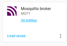
Click on all the entities link in the tile and select all the entities you want to get data for. When you are done, click ENABLE SELECTED.
Now do a reboot of both HA and the H66 (it doesn’t hurt).
Now you should be ready to make dashboards and use the sensors.
Also, check this tutorial out: https://learn.adafruit.com/set-up-home-assistant-with-a-raspberry-pi/mqtt-setup
(Disclaimer: you do everything on your own responsibility. The information given may be incorrect. By interfacing to your heat-pump you may change settings that may lead to overheating and/or damage of your heatpump, loss of heat or other problems. If you do not know what you are doing, don’t do it).
Earlier versions of orbi RBS350 (satellite) and RBR350 (router) before ca. version 4.4.1.29xx would have to be set up in chained mode manually. If you have a house where one part of the house does not have coverage from the base the system will now automatically set it self up in chained mode. IN the outermost nodes you even have BOTH 2.4GHz and 5GHz service for the units that want to connect even if the back-haul is wireless and uses 2.4 or 5.
If you have experienced that some units on your Wifi network that were previously connected to your fiber or cable router cannot anymore be connected on your internal network – after you installed a set of ORBI mesh units – the reason may be that the ORBI system is not set up in access point mode. If it is set up in router mode, there is an internal firewall that acts in addition to the normal firewall you have in your cable or fiber modem. Log into the orbi unit with orbilogin.com and go to ADVANCED/Advanced/Router/APmode and select AP mode. Reboot the ORBI units and you are all set. All units on your Wifi network are visible (on your internal network). Read more here: https://kb.netgear.com/000061927/What-is-the-difference-between-router-mode-and-AP-mode
Have you ever wondered how to use a psychrometric chart? With this tool you can convert from relative humidity (RH) to absolute humidity (gram water per kilo air). Reference: Perry Peralta NC State University. Full credit goes to the author of the slides.
You can also click the download link if you want to view the document on your laptop or mobile device.
Power on HA
Have a screen and a keyboard connected
When you see the ha> prompt enter login
Then do this:
nmcli radio

Now scan and list available wifi access:
nmcli device wifi rescan
nmcli device wifi

Use quotes around your ssid and password:
nmcli device wifi connect "YOUR_SSID" password "YOUR_WIFI_PASSWORD"
This will try to connect to your SSID and will generate a network profile for you if successfull.
The output will be similar to"Device 'wlan0' successfully activated with...."
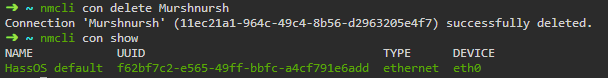
nmcli con show

You should be seeing at least two profiles and both green.
If you are seeing some profiles you’d like to get rid of you can remove them using:
nmcli connection delete CONNECTION_NAME
These may have two separate ip addresses on your network: one for ethernet, one for wifi.
You can check the ip addresses using:
ip addr show
Now connect to http(s)://your_wifi_ip:8123 in your browser.
Credit goes to: https://community.home-assistant.io/t/guide-connecting-pi-with-home-assistant-os-to-wifi-or-other-networking-changes/98768

