How to remote login to your raspberry pi via Windows native Remote Desktop Connection:
https://www.maketecheasier.com/enabling-remote-desktop-access-on-raspberry-pi/


How to remote login to your raspberry pi via Windows native Remote Desktop Connection:
https://www.maketecheasier.com/enabling-remote-desktop-access-on-raspberry-pi/
You can now logon to Raspberry PI via the windows builtin remote desktop connection! WIth XRDP there is no need for other software to be installed. However the Norwegian keymap is not there by default so your _ / @ keys etc may be messed up.
You need to edit your /etc/xrdp/xrdp_keyboard.ini file with
sudo nano /etc/xrdp/xrdp_keyboard.ini
Then add the lines marked in bold below. As far as there is a km-00000414.ini file in the /etc/xrdp/ folder you are good to go. The windows remote desktop client will send info that you use a norwegian keyboard when you log on and the XRDP service on Raspberry will use the correct keyboard mapping to X
Edited: xrdp_keyboard.ini file
;
; RDP Keyboard <-> X11 Keyboard layout map
;
; How this file works:
; 1. load the file and scan each section to find matching “keyboard_type”
; and “keyboard_subtype” based on the values received from the client.
; If not found, then jump to default section.
; 2. in the selected section, look for “rdp_layouts” and “layouts_map”.
; Based on the “keylayout” value from the client, find the right x11
; layout value.
; 3. model/variant are inferred based on the “keyboard_type” and
; “keyboard_subtype”, but they can be overridden.
;
;
; RDP Keyboard Type (http://msdn.microsoft.com/en-us/library/cc240563.aspx)
;
; 0 is not a valid value
;
; 1 – IBM PC/XT or compatible (83-key) keyboard
; 2 – Olivetti “ICO” (102-key) keyboard
; 3 – IBM PC/AT (84-key) or similar keyboard
; 4 – IBM enhanced (101- or 102-key) keyboard
; 5 – Nokia 1050 and similar keyboards
; 6 – Nokia 9140 and similar keyboards
; 7 – Japanese keyboard
;
; RDP Keyboard Subtype is vendor dependent. XRDP defines as follows:
;
; 0 is not a valid value
;
; 1 – Standard
; 2 – FreeRDP JP keyboard
; 3 – Macintosh
; … – < any vendor dependent subtype >
;
; The list can be augmented.
;
; default
[default]
; keyboard_type and keyboard_subtype is not read for default section. It
; is only a placeholder to keep consistency. Default model/variant are
; platform dependent, and could be overridden if needed.
keyboard_type=0
keyboard_subtype=0
; user could override variant and model, but generally they should be inferred
; automatically based on keyboard type and subtype
;variant=
;model=
; A list of supported RDP keyboard layouts
rdp_layouts=default_rdp_layouts
; The map from RDP keyboard layout to X11 keyboard layout
layouts_map=default_layouts_map
[default_rdp_layouts]
rdp_layout_us=0x00000409
rdp_layout_de=0x00000407
rdp_layout_fr=0x0000040C
rdp_layout_it=0x00000410
rdp_layout_jp=0x00000411
rdp_layout_jp=0xe0010411
rdp_layout_jp=0xe0200411
rdp_layout_jp=0xe0210411
rdp_layout_kr=0x00000412
rdp_layout_ru=0x00000419
rdp_layout_se=0x0000041D
rdp_layout_ch=0x00000807
rdp_layout_pt=0x00000816
rdp_layout_br=0x00000416
rdp_layout_pl=0x00000415
rdp_layout_no=0x00000414
; <rdp layout name> = <X11 keyboard layout value>
[default_layouts_map]
rdp_layout_us=us
rdp_layout_de=de
rdp_layout_fr=fr
rdp_layout_it=it
rdp_layout_jp=jp
rdp_layout_kr=kr
rdp_layout_ru=ru
rdp_layout_se=se
rdp_layout_ch=ch
rdp_layout_pt=pt
rdp_layout_br=br(abnt2)
rdp_layout_pl=pl
rdp_layout_no=no
; if two sections have the same keyboard_type and keyboard_subtype, then
; the latter could override the former.
[rdp_keyboard_mac]
keyboard_type=4
keyboard_subtype=3
rdp_layouts=default_rdp_layouts
layouts_map=rdp_layouts_map_mac
[rdp_keyboard_jp]
keyboard_type=7
keyboard_subtype=2
model=pc105
rdp_layouts=default_rdp_layouts
layouts_map=default_layouts_map
[rdp_layouts_map_mac]
rdp_layout_us=us
rdp_layout_de=de
rdp_layout_fr=fr
rdp_layout_jp=jp
rdp_layout_kr=kr
rdp_layout_it=it
rdp_layout_ru=ru
rdp_layout_se=se
rdp_layout_ch=ch
rdp_layout_pt=pt
rdp_layout_br=br(abnt2)
rdp_layout_pl=pl
Credit to this post where I found the info that solved it for me: https://www.raspberrypi.org/forums/viewtopic.php?t=181873
Sometimes there are bugs or special corner conditions that makes a NAN (Not A Number) occur in code compiled from a C++ source and executed on an embedded systems without memory to run exception handlers.
Here is what @Jalf writes over at StackExchange:
According to the IEEE standard, NaN values have the odd property that comparisons involving them are always false. That is, for a float f, f != f will be true only if f is NaN.

Note that, as some comments below have pointed out, not all compilers respect this when optimizing code.

For any compiler which claims to use IEEE floating point, this trick should work.
Sometimes there is a need to spread code into several .cpp files to avoid clutter (for example main.cpp, other1.cpp, other 2.cpp) . So if you implement a function in a separate .cpp file, how do you access objects instantiated in main?
Solution: use extern
other1.cpp:

extern ObjectType objectname

void doSomething (void)
{
      objectname.method();
}
Of course this is very basic stuff, but many new programmers ask about this so I included a short post about this here.


Rock Seven has launched a board that takes care of the PSU and antenna requirements to support the Iridium 96090 module https://www.iridium.com/products/iridium-9602/
http://www.rock7mobile.com/products-rockblock.php?gclid=EAIaIQobChMI1ZWSqv2C3gIVRawYCh2DBQ7eEAAYASAAEgI3vfD_BwE
This enables fast time to market and coverage in remote areas on customers IoT devices.
If you are looking for a Zumstar + PiSpot setup guide for DMR, then KC6N has made a great tutorial that is available here as a .PDF: https://www.hamdigitaal.nl/download/algemene-informatie/ZumSpot_Pistar_KC6N_20180605.pdf Full credit goes to KC6N, I have taken the liberty to link to the site where this document is available to help other amateur radio ops get on the air with their hotspot setup.

LDG does not specify either max C or max L of their antenna tuners in the “pro” series. They specify a vague “it can tune 1000 ohms”. This basically means nothing as no frequency is given and it is not given if they mean R or X or Z by “1000 ohms”. There is also no service manual or schematic available. Very disappointing from a serious (?) supplier.
Well, since LDG doent specify anything, I have measured it.
The LDG AT-100PROII is a series L, shunt C configuration.
Min L is 3uH, max L is 11,8uH
Min C is 85pF, max C is 250 pF
This is measured at 2MHz.
This shows that the capability of tuning an 2x20m doublet via “10-12m” of 590 ohm ladder line on 80m seems to be limited, and that tuning on 160m is very difficult.This is mainly due to limited Lmax. Also the limited Lmax gives limitations on other bands as well. Having the proper length of transmission line is important to overcome this limitations. You MAY also use a 4:1 or 9:1 balun. However it is important that the balun does have a very low loss. (Otherwise you you end up with a good SWR but poor efficiency).
I recently bought a second hand Icom IC-7100 HF radio for a reasonable price. This radio is known for a very conservative approach to internal ALC on the power output. This causes the output power to not go above approx 75-80W (PEP) as measured on my LPA-100 wattmeter in PEP mode with 14,5V DC input. Of course, there is no need to overdrive any linear amplifier, however Icom engineers have probably overdone it a bit on the conservative side on this radio (?).
There are two published mods that are possible on this radio. I did only one of the mods that involves a jumper from C1509 to ground, because the other mod that involves a 10uF capacitor is reported to cause modulation issues on FM and AM.
The PEP output power increased from 75-80W PEP to approx 140-145W PEP (14,5V DC input). Note: PEP, not average. On a sidenote the peak to average ratio also improved. There is no need to have PEP output of more than 100-110W PEP by the way.
The mod is easy:
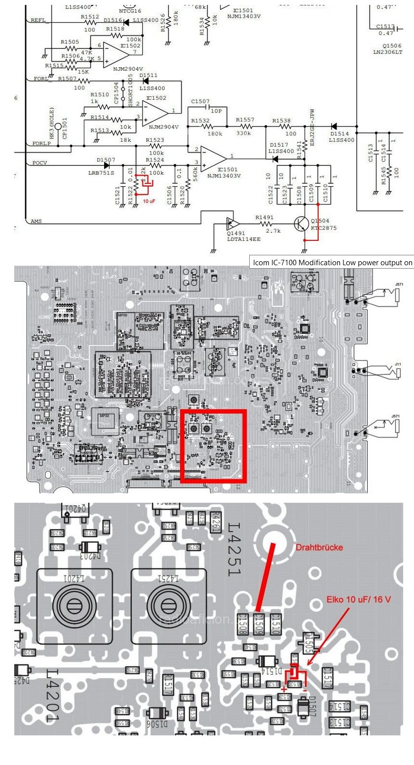
IC-7100 mod. (I did steal this picture from radio aficion website)
I did also upgrade the firmware to :
The firmware upgrade did have a small but insignificant effect on the PEP output power according to what I found. The hardware mod, did have a signficant impact as the DSP is led to believe that the output power is lower than it is.
Disclaimer:
Hvis du vil sette opp et 4G IP kamera, en 4G alarm, eller kjøre amatørradio via 4G remote så må du sette opp 4G ruteren din slik at datatrafikk UTENFRA kan komme inn igjennom 4G ruteren. For å kunne få dette til å virke må du kjenne IP adressen til 4G ruteren din. Ringer du Telenor support får du som regel et “god dag mann økseskaft svar”. Ringer du “telenor eksperten”, så får du ofte et nytt “goddag mann økseskaft svar”, men denne gangen må du betale for det! Denne quick guiden omhandler Telenor D-link DWR-961 ruter.
Utfordring 1: Telenor har satt opp sine 4G rutere per default slik at du ikke har en egen IP adresse som er synlig på internett. Datatraffikk utenfra blir også stoppet (av sikkerhetsgrunner – som regel har ikke vanlige brukere behov for at traffikk utenfra skal kunne komme igjennom om den ikke er initiert innenfra først).
Løsning:
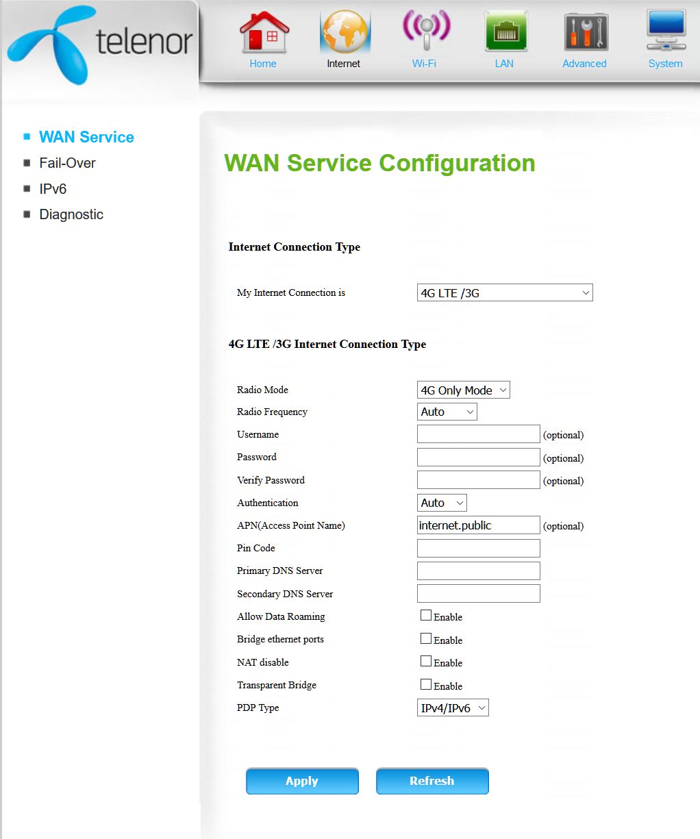
Utfordring 2: IP adressen er ikke fast så den endrer seg hele tiden. Du aner ikke hvilken ip adresse 4G modemet ditt og det utstyret som står tilkoplet på innsiden har…. hvordan skal du da kunne aksessere dette?
Løsning:
Håper dette var til hjelp. Ønsker du hjelp til en kommersiell installasjon, IoT eller liknende så kjenner jeg firmaer som kan hjelpe med dette. I så fall ta kontakt så kan jeg formidle info.
I have successfully got FT891 running under TRX-manager: http://www.trx-manager.com/index.html
1) Install the dual serial port driver from Yaesu website.
See manual here: http://www.yaesu.com/airband/downloadFile.cfm?FileID=9515&FileCatID=42&FileName=USB%5FDriver%5FInstallation%5FManual%5FENG%5F1610%2DB0.pdf&FileContentType=application%2Fpdf
(Note: the 891 has dual serial ports, it does not have an USB soundcard).
2) Reboot the PC and check that you see two serial devices in your Device manager (type device manager when clicking the start button)
3) Hold F on the FT-891 in a couple of seconds (long click)
4) Goto menu 05-06
Set CAT RATE to 38400
6) Goto menu 05-08.
Set CAT RTS to DISABLE (unless you do that you may have a problem getting data thru)
7) Set the rate to 38400 in TRX-manager (setup menu) and select FT-891. Also select correct COM port (on my PC it was COM5. It may be different on yours).
Remember: unless you set CAT RTS to DISABLE (see above) you will not get data thru and you will mess around in the TRX-manager menus while the problem was a setting in the FT-891 menu.
8) Stop and restart TRX-manager
9) You may hear a clicking sound for every CAT transmission in your FT-891 loudspeaker (A bit annoying… I have to admit that even if I like Yaesu radios)
10) Click F on the FT-891 (short click)
11) Goto MON on the FT-891 menu
12) Click on MON
13) Turn down the MON level to 0
Note: This applies regardless if you have MON ON or MON OFF (this is a bug in Yaesu’s firmware. Rare. LOL)
14) Now you have CAT control without any clicking sounds on your FT-891
15) Enjoy your Yaesu FT-891
Comments about the FT-891:
Plusses: the FT-891 has in my view a better and more modern RX than the ageing FT-857, even better than IC7300 (some ppl. claim) http://www.eham.net/reviews/detail/13042?page=2 , it is a low cost modern mobile 100W HF rig with a small detachable front, it has DSP RX, a nice variable RX filter, works well down to low voltages even if someone claims it doesn’t, has a much better menu system and a better VFO, it has a reasonable current draw on RX (even if the datasheet overstates this a bit it is below 1A on my rig).
Minuses: No VHF or UHF ( however that may be a benefit. Not the compromises that probably are in the 857 rf chain). No USB soundcard (do you really need that in a mobile station?), 60M USB has to be programmed in a memory and you go memory tune from there and it will keep USB even if you are below 10 MHZ.