CG-3000 antenna tuner. High resolution schematic diagram

The CG-3000 is a clone of a SCG tuner. It uses a PI network for tuning. There are many schematic diagrams on the Internet. However 95% of those have so low resolution that they are not readable when you zoom in. I finally found a schematic with enough resolution to show the component values. It is the output circuit that receives the highest voltages when matching a high impedance antenna and those are the most likely to be damaged. To be proactive I changed mine to 6KV types low loss Vishay Cera Mite and TDK CC45SL3 types. Below you can find the schematic, should you need to repair your tuner.
If you need to change components in the output circuit and want quick info, all the capacitors are either 100pF or 50pF ceramic. There are series and combinations of from right to left 4x100pF par, 2x100pF par, 2 x 50pF par, 2 x 100pF ser, 2 x 50pF ser. This gives the values 400pF, 200pF, 100pF, 50pF and 25pF. The relays can then switch in several combinations from 25pF to 775pF. Note that the schematic does not show that the 100pF cap is two 50pF in parallel, that the 50pF is two 100pF in series, that the 25pF is two 50pF in series. I may have an older or newer hw version than the schematic.

Repair of LDG automatic antennatuner

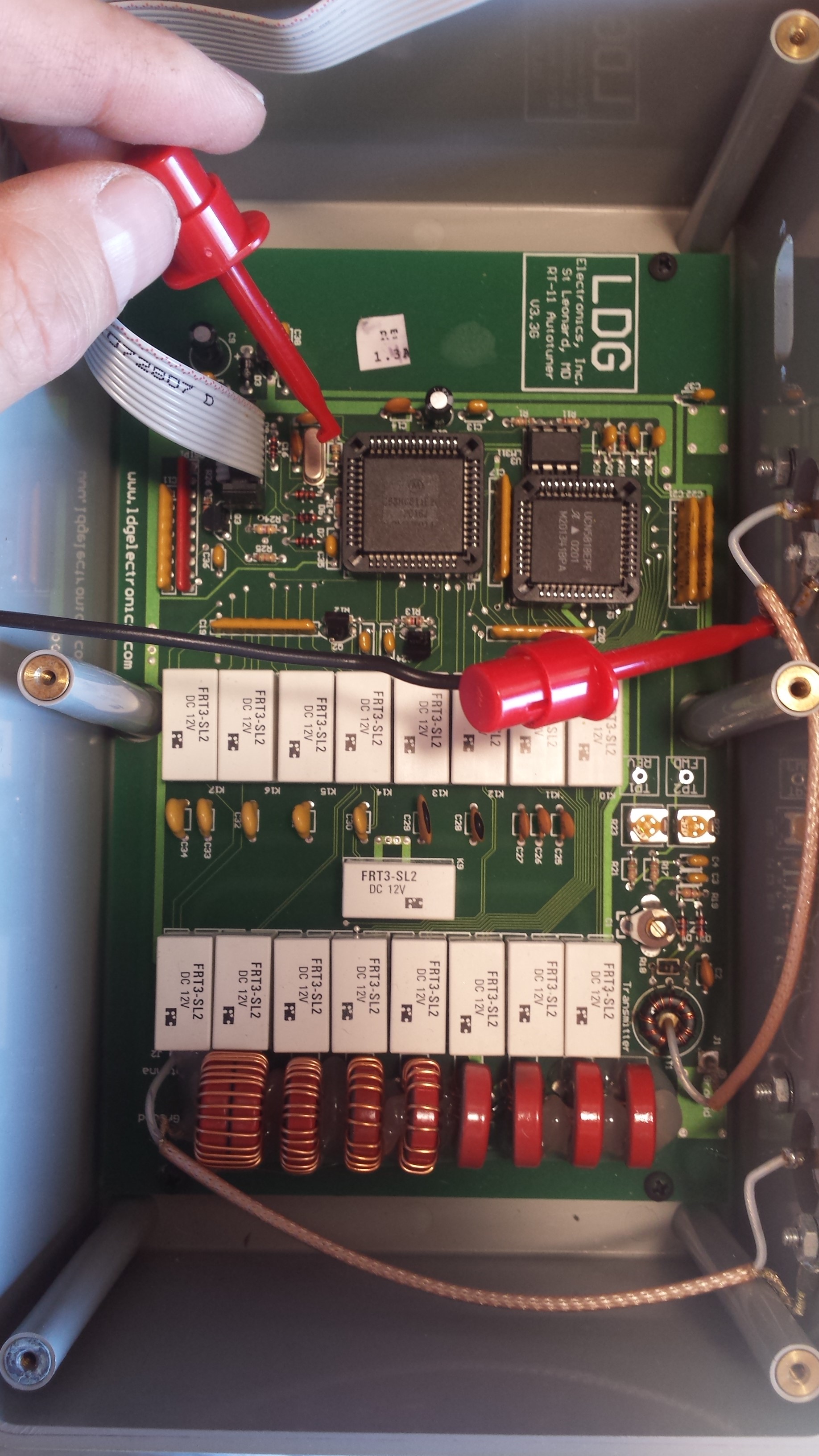
I blasted my LDG antennatuner some time ago. Or …. I thought I blasted it….. It appeared that it was only the resistor in the SWR detector circuit that got burned out. I replaced that resistor and now its ok again.It was easy to repair. However these small LDG tuners dont take more than 100W max. The designers have used ferrite cores, whereas it would have been a much better idea to use carbonyl cores or air core inductors. The latter doesnt get so easily saturated.

20150828_113855 20150828_102444 20150828_102215 20150828_101339

However I must say that the design of the LDG equipment I have seen so far is not very impressive. Why use that BIG chasis when you dont need it? Why use DB9 style connectors on a chassis that is supposed to be watertight? Look at that coax termination there. Both on the board and on the PL259 chassis connector. Why use RG174 teflon coax when you have such crappy terminaions? Perhaps it would be better with no coax at all 🙂 However when the tuner works it works fairly OK. Just dont trust this kind of equipment in a contest or on a dx expedition.