HDSDR trackerball VFO project

I have been working on a trackball based controller for my HDSDR SDR project lately. This is a small R&D project that is run on my spare time where the goal is to determine if it is possible to use a trackball as a VFO for software defined radio (SDR) in contests. The project started out based on a demand for a more ergonomic way to operate a mult receiver in a contest environment that is less fatiguing during 48hours duration of a major contest like CQWW or CQWPX. The goal is that it should be possible to operate all radio functions you need from one hand only: VFO, speed of vfo, band, mode, filter width, volume, gain. I have modified a Marconi trackball and the controller is a Trinket Pro controller (Arduino)

20151219_131116 20151219_130846 20151219_123341 20151219_163343
20151217_211347 20151217_211710

20151219_153628


RF current amperemeter with log detector

I have long had the need to measure antenna current. This can be done by a rf-current transformer and a rectifier made by a shottky diode or fast silicon diode and an integrator driving a mechanical instrument. However the dynamic range is very limited with such a setup.

Therefore I made a new rf-amperemeter design with a log detector chip from Analog Devices driven from a current transformer made out of a split core ferrite material that has response in the HF and lower VHF frequency range.The current trafo is terminated in a few ohms and the RF current conductor (actually the primary) sees only a fraction of an ohm so very little influence is done on the circuit you are measuring. (Apart from capacitive coupling and a slight leakage inductance from the current transformer windings/ferrite combination). The ferrite core is a split type and is epoxied to a clip.

I calibrated the instrument by terminating the generator in a fancooled 100W dummy load and measured the voltage over the load by an oscilloscope. Since it has a log output the dynamic range from milliamp range up to 1,4A RF current. That would peg a mechanical instrument if you would at the same time want to be able to detect a significantly lower RF-current without having to change scales with switches / pot meters etc.

Next I plan on making a OLED display on this design with an arduino controller. Its a sparetime project so lets see how long tiem it takes before I implement that.

20151028_171941 20151028_171934 20151028_123754 20151028_123344 20151028_123330 20151028_111539 20151028_111534 20151027_222849 20151027_222832 20151027_222828 20151027_222353 20151027_222327 20151027_193055 20151027_151301 20151027_151250 20151027_123354 20151027_123343 20151027_123332 20151027_112816 20151027_112802 20151027_112746

Single Sideband (SSB) modulation on the Raspberry PI

F5OEO has recently written some code to transmit a SSB signal using just the hardware in the Broadcom SOC chip on the Raspberry Pi.  You can find more info on this link http://www.rtl-sdr.com/transmitting-fm-am-ssb-sstv-and-fsq-with-just-a-raspberry-pi/

I tested the code on my RPI on 6m via a cable connection. It worked OK. If you look at the S-meter you can see that the envelope is constant. This is due to that the RPI has no way of modulating the envelope so the software actually modulates frequency. It is kind of constant envelope SSB.

Below you can see what the signal looks like. (This is received on a SDR via an attenuator). The signal is a bit too wide. However cool test.

20151101_214334
If you want to test the code yourself you can check it out over on F5OEO at github https://github.com/F5OEO/rpitx

Warning: do not connect the RPI GPIO output running this code to an external antenna without a bandpass or lowpass filter and a valid amateur radio license. Never transmit any signal outside the amateur bands.

How to upgrade your Windows installation without an internet connection

Sometimes the need arises to upgrade an old Windows installation. If you do have a slow internet connection or no internet connection, this may be a significant time problem. A full Microsoft download of SP3 and all hot fixes can take many hours on a slow Internet connection. Perhaps you now think: why is this relevant? I always have a fast internet connection, don’t I? But is this in fact true? What about at  a customer site with a slow DSL connection. What if the internet connection is down? What if it is an embedded system? What if you are installing from an old XP pre SP1 DVD where the new Microsoft Update methods are not supported? Well, in those cases you need WSUSOffline that can be downloaded from http://www.wsusoffline.net/ This is a set of scripts that automatically downloads the service packs, hot fixes, .NET frameworks and language support you need from Microsoft’s servers. You can select what components to install (se below image). The install files together with an installer script can be copied onto a USB memory stick. When you run the installer script on the machine you want to upgrade, everything happens automatically and you will, when the process is finished, have a fully updated Windows installation. I used this to upgrade an old machine with an old outdated XP installation on, for use with my CNC machine numeric control software.

Testing DxPatrol HF converter for Funcube dongle

DSC_6989

At Hamradio in Friedrichshafen I picked up a DxPatrol HF converter for the Funcube Dongle ( Supplier WiMo, designer: http://www.ct1ffu.com/site/ ). I was eager to test it on HF CW reception. To check the coarse frequency and operation of the local oscillator I used my Yaesu VX7R for detecting the signal from the board. (The DxPatrol HF converter can be given a voltage feed via the SMA from the Funcube Dongle, if you turn it on from your Funcube. Alternatively, you can feed it with power via the USB connector – only 5V and GND is connected internally of course. I wanted to check that the converter was operating by listening to the local osc with my VX7R).

DSC_6988 DSC_6990

I was a bit surprised over the test result when listening to CW signals on HF. All the signals on the bands sounded like russian stations from the old days derifting all over the place. The local oscillator of the DxPatrol I purchased is unstable. It drifts so much that it can clearly be heard on CW. The designers of the DxPatrol unit told me to keep the unit free from wind when I asked about a possible design or osc issue via mail hehe 🙂 . I think a “slight mod” may be necessary … I have SI570 and a buffer in my mind….

Collinear airband antenna design

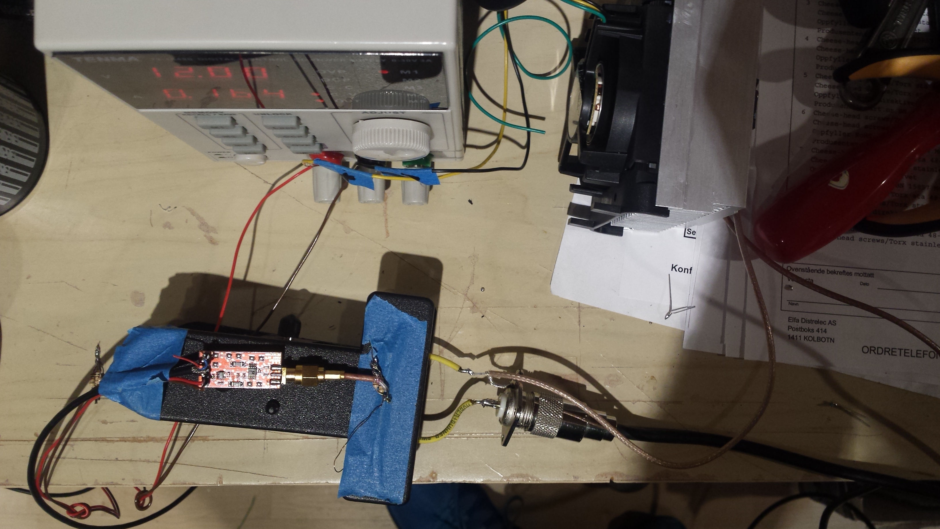
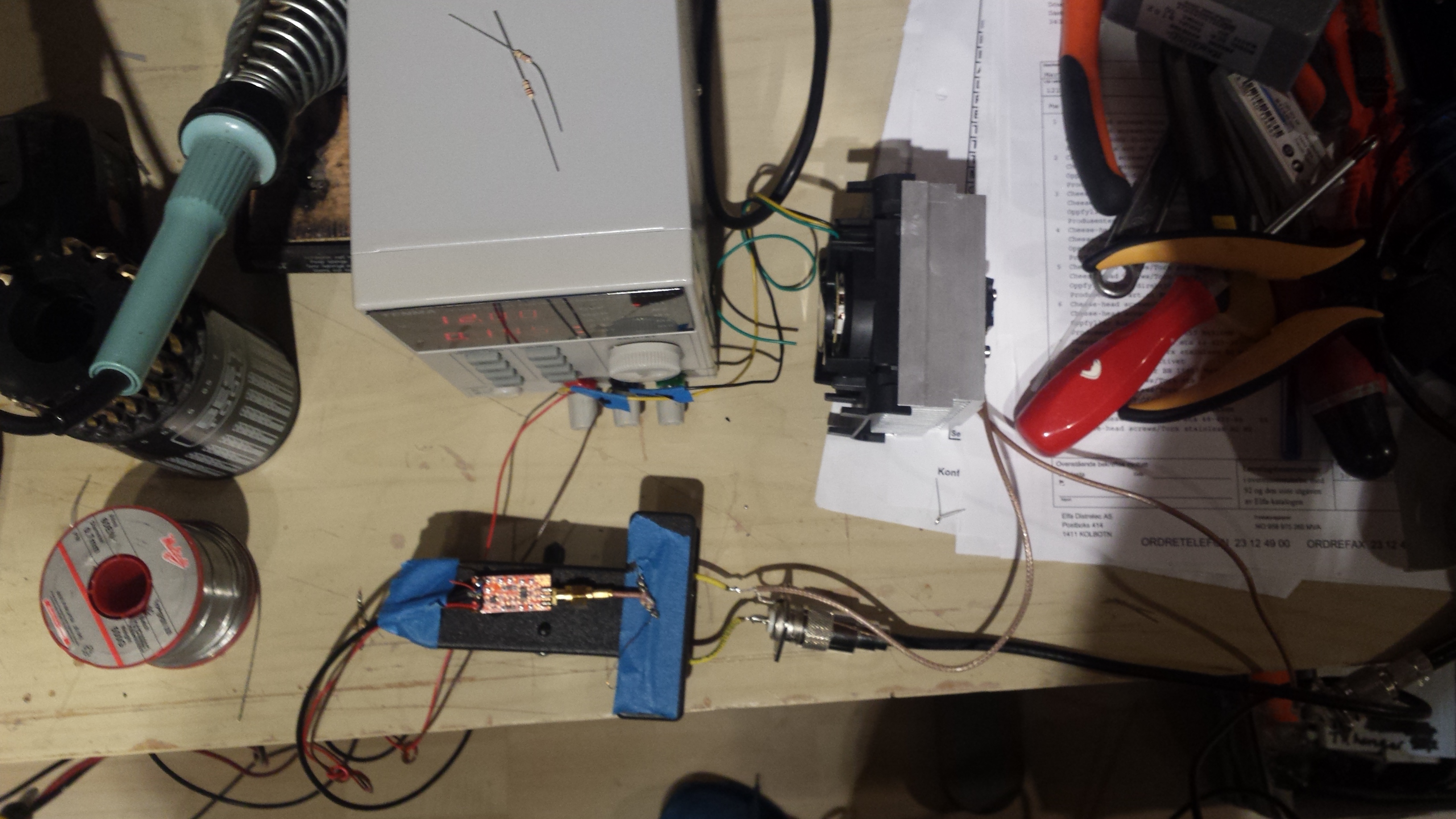
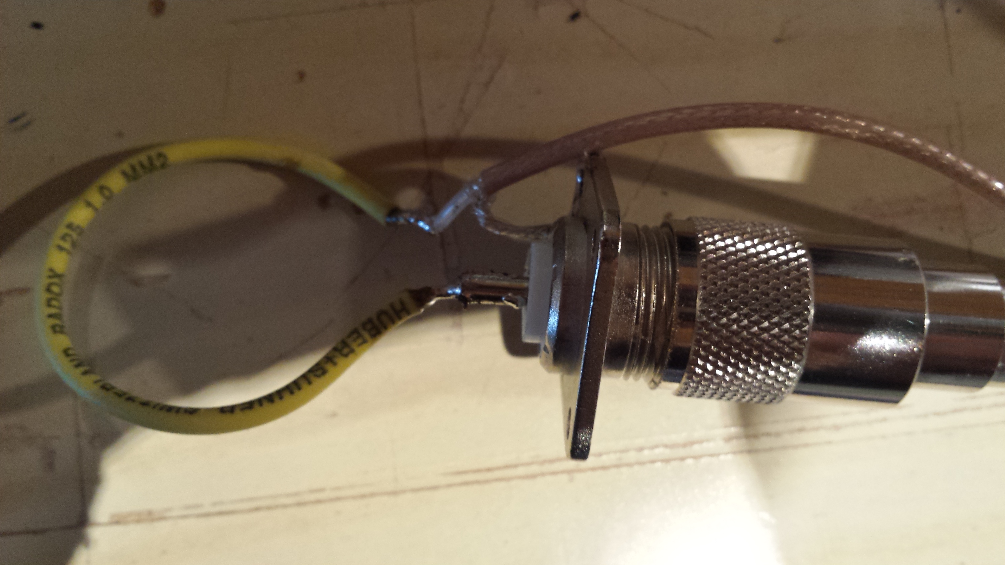
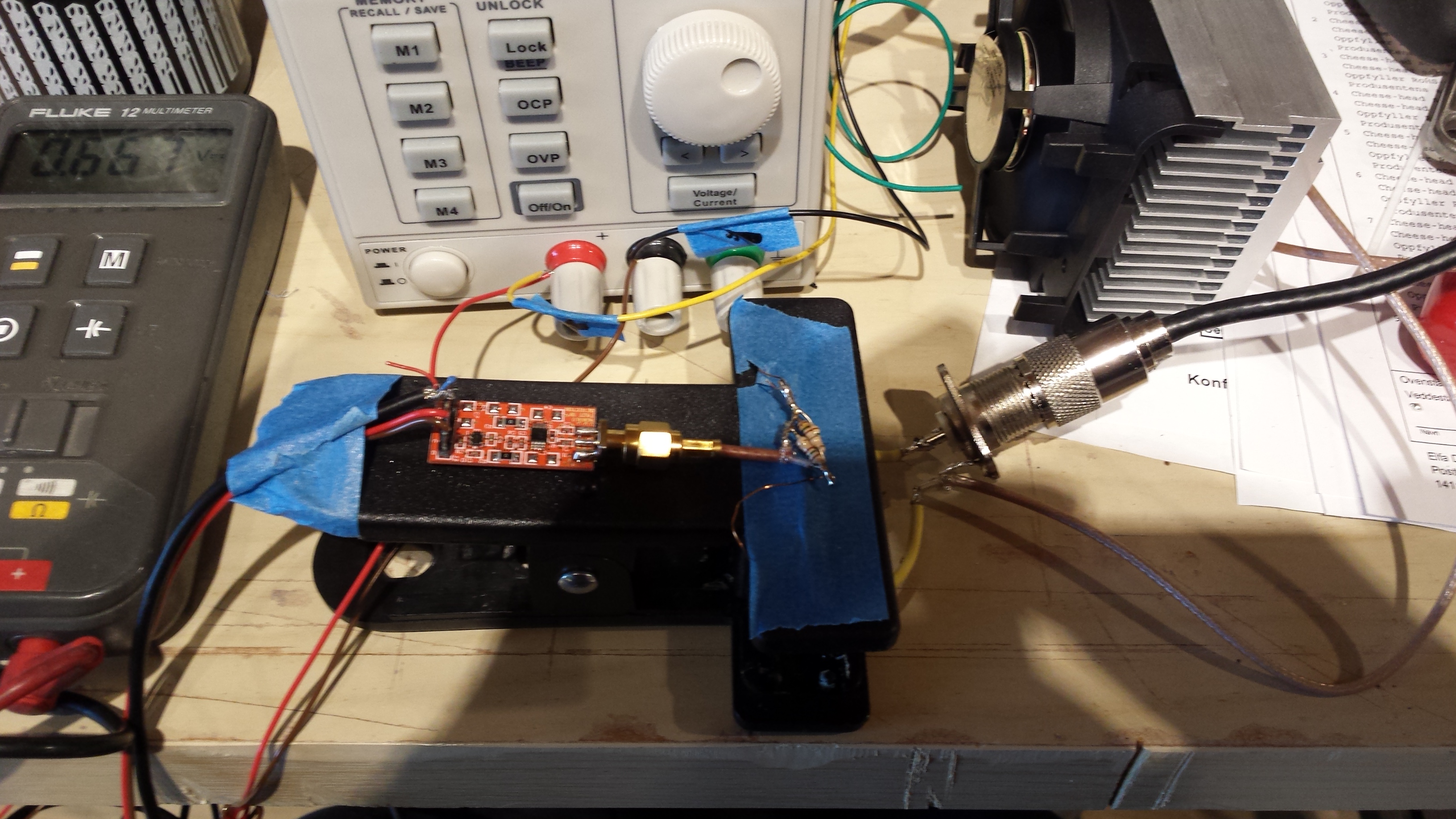
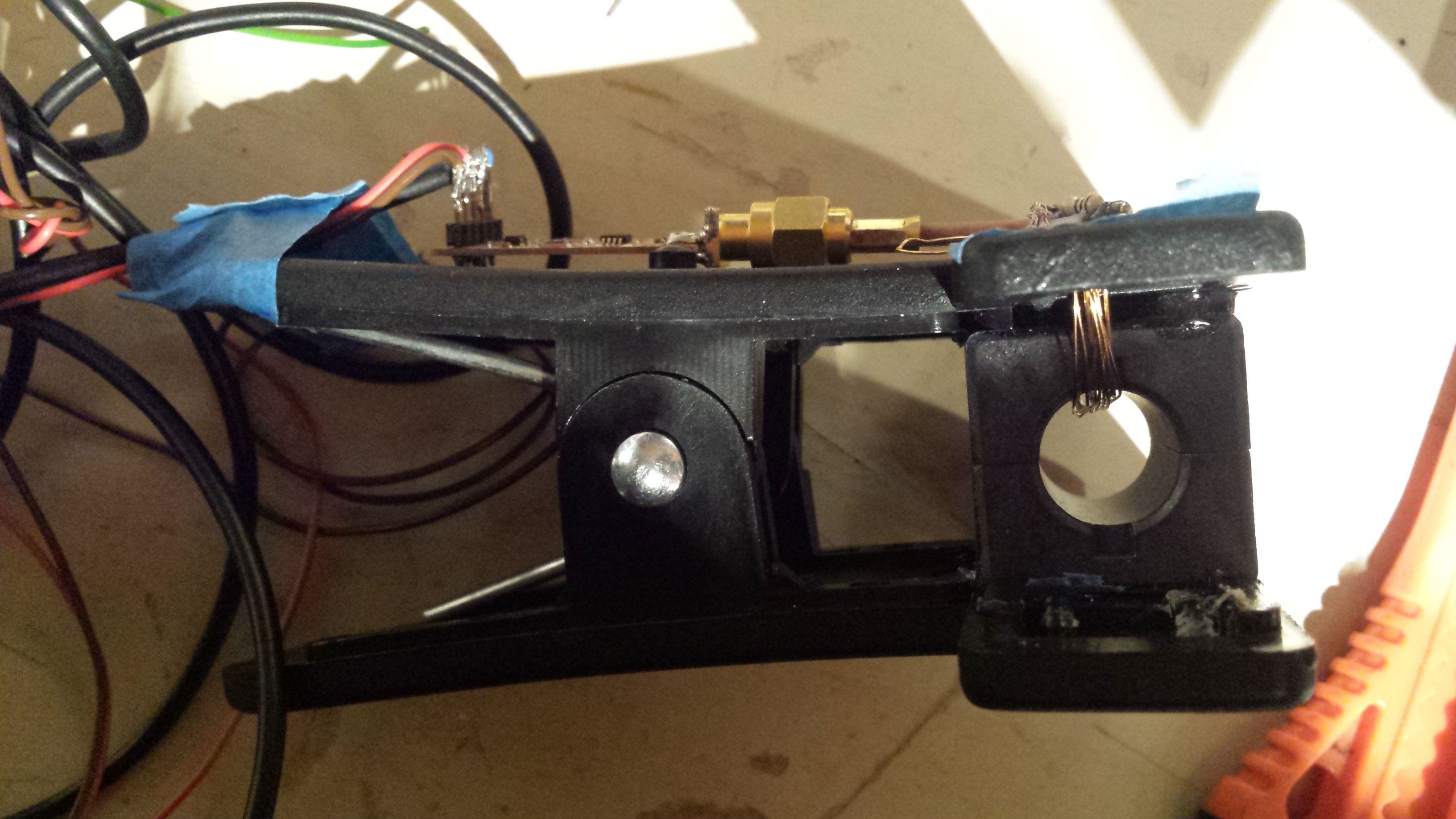
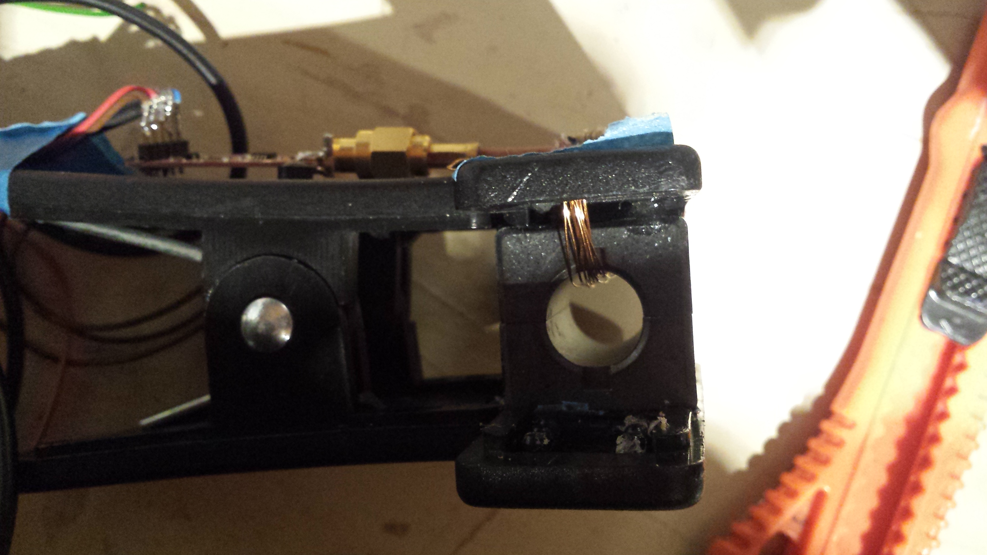
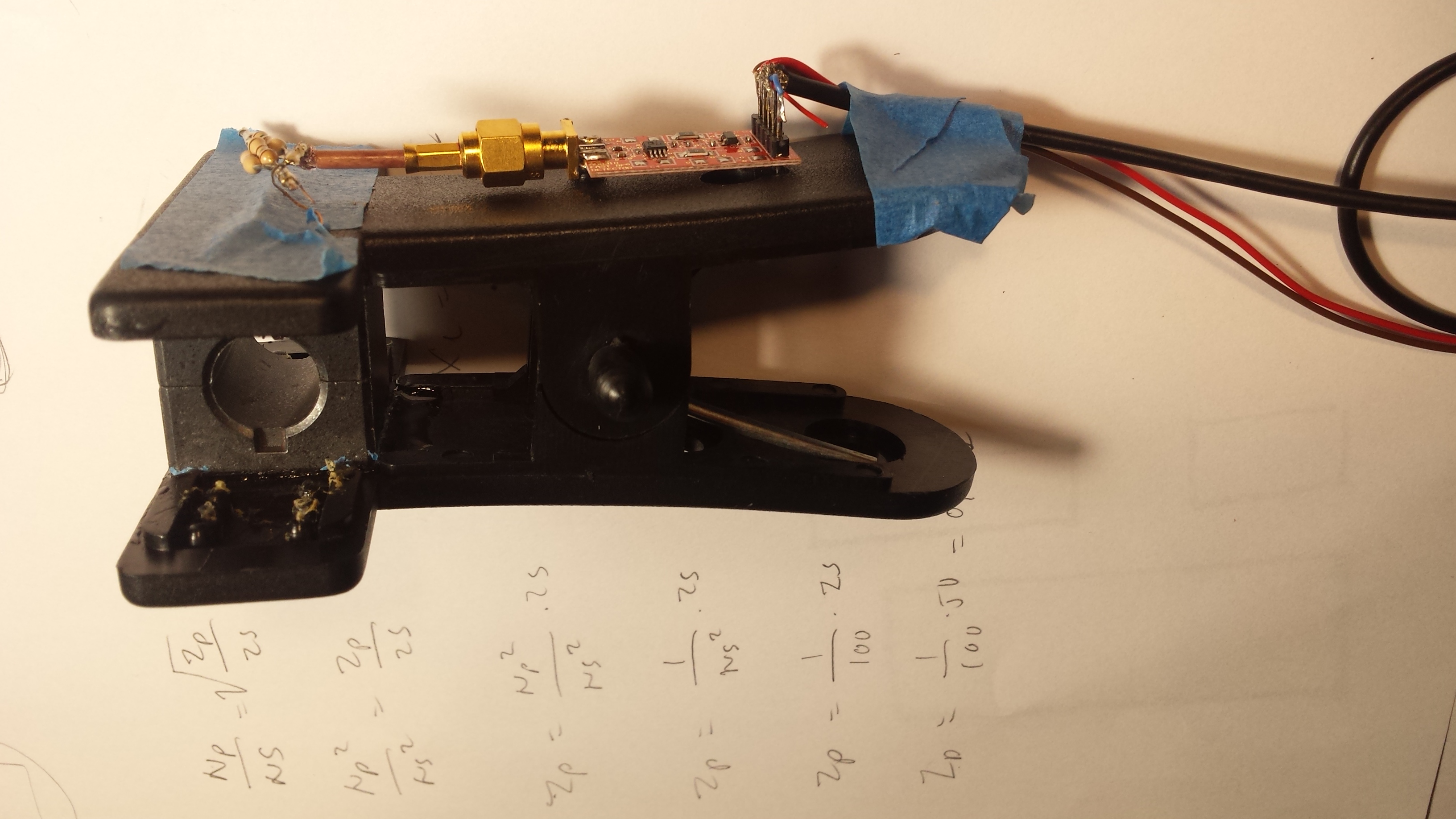
I wanted to test a simple airband antenna design since I had a roll of balanced feedline laying around in my shack doing nothing useful. First I had to measure the velocity constant of the feedline with my MFJ-259 to be able to come to an estimate of the required length of the matching section. I could also have used my vector network analyzer (VNA) to do that by the way.  To measure without interference from coupling to adjacent objects I did the measurement with the cable hanging out from my balcony as you can see in the left picture. The MFJ-259 was connected in the end and held by hand (that is a benefit of the battery operated MFJ 259 even if the instrument is not of the most accurate on the market). I wanted to make two antenna segments folded over each other. Therefore the top of the feedline is shorted and the currents will be in phase if the antenna is of a proper length. The matching section is a shorted line section that is tapped by the transmission line. The coil on the coax is a choke (I haven’t done any measurements on that choke yet by the way).

DSC_5052DSC_5054DSC_5074  DSC_5076DSC_5064DSC_5050

The procedure I used to find the velocity factor of the balanced transmission line was to first measure a length of the feedline with a tape measure. Then I connected the MFJ-259 and found the frequency where the lowest reactance could be measured. (See pic two from left on the upper row above. You can see that the X is very low). This was done in the mode of the MFJ-259 where it is possible to measure both R and X. This is the quarter wave frequency of the line when the wave propagates in the line – not in the free air (“ether”). Then I calculated that frequency back to the wavelength with  y=300/f. I then divided the tape measure length by the calculated length and came to a velocity factor of 0,89. This is the ratio of the wavelength in free air and the wavelength in the transmission line. This is directly related to the propagation speed of the line when it operates in transmission line mode. From that I calculated the required length of the matching transformer and the approximate tapping point on that transformer to reach 50 ohms. Please note that you cannot use the velocity factor of the transmission line to calculate the required length of the antenna (only the matching section), since the RF currents on the two folded legs on the antenna are in phase and therefore the one lead is coupled to the ether and not to the other lead.

lb3hc_airband_ant

The picture above shows the SWR as measured with my vector network analyzer from DG8SAQ. The markers on the right side shows a 1:2 SWR bandwidth of 118,5 to 128,6 Mc/s which is OK. The reference level is 1:1 SWR. This level is lifted one division for clarity. (I think the Mc/s  is a cool way to express frequency by the way.)

DSC_5098

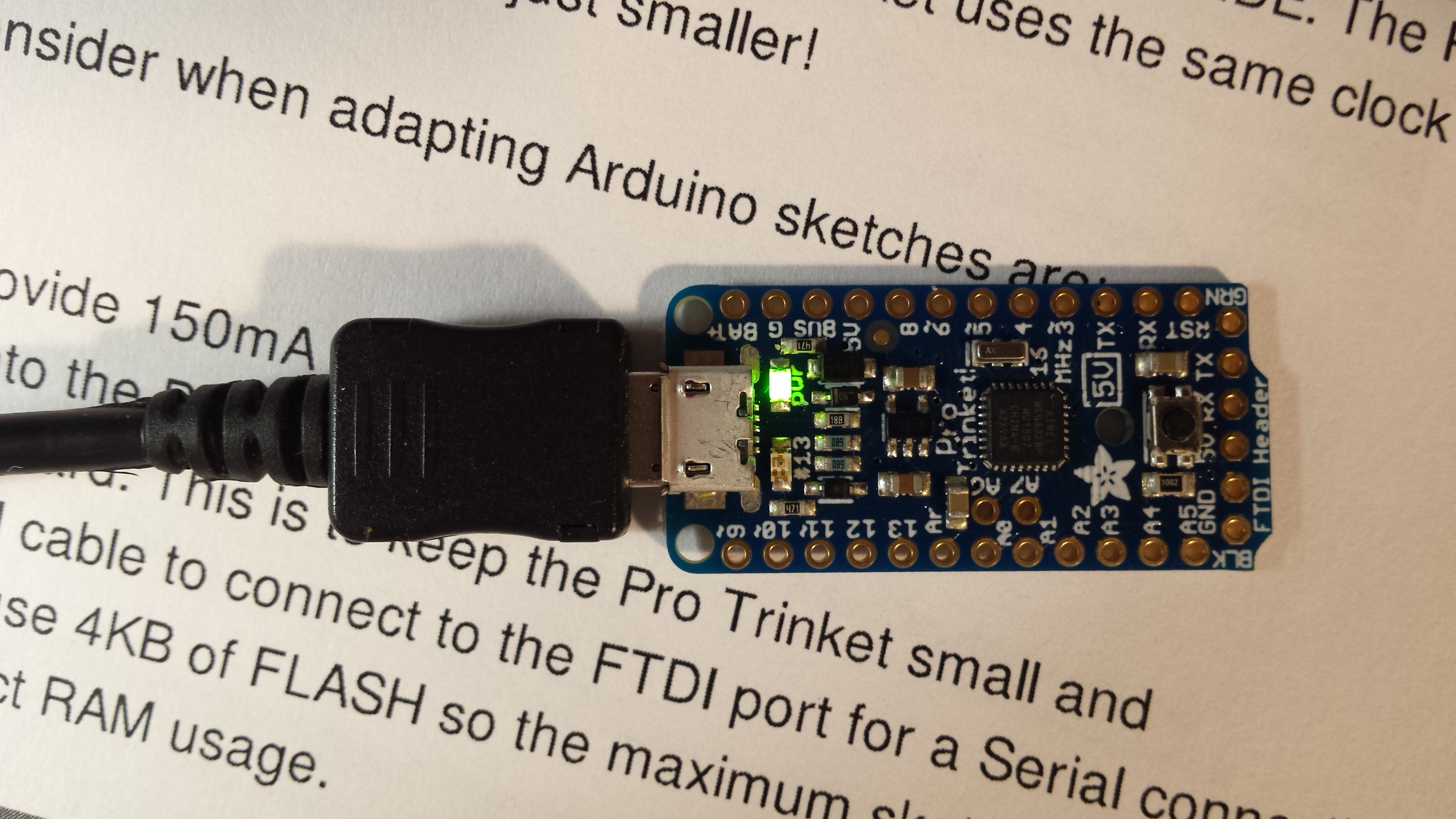
Here my DG8SAQ1 kc/s to 1,3 Gc/s VNA is shown. It is connected to my PC via USB.

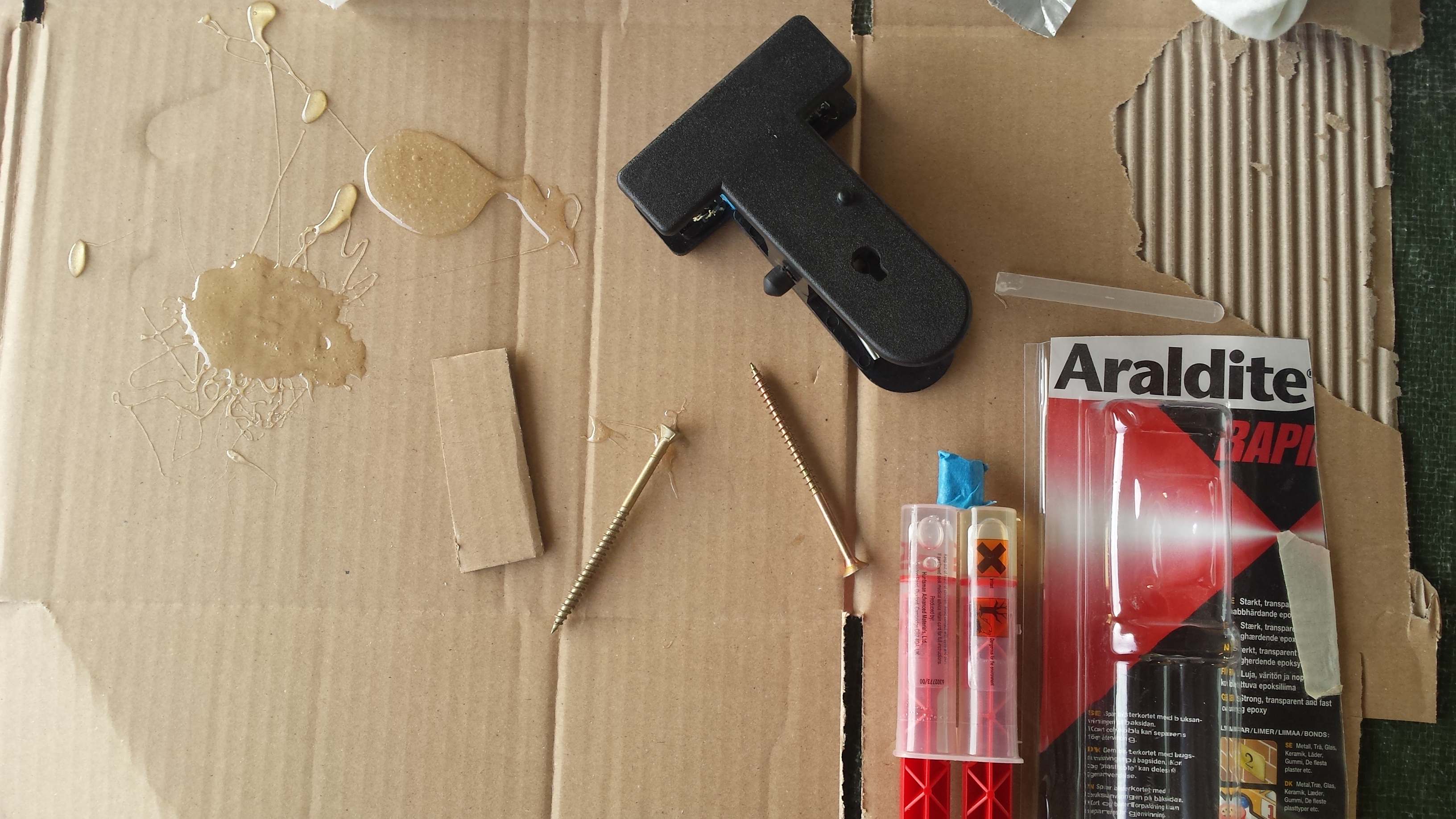
Conclusion: a combination of the MFJ-259, the DG8SAQ vector network analyzer, some balanced line and some coax can be used to make a good collinear airband antenna in less than one our at a cost of a few dollars. The antenna was screwed to a wooden section of my roof by a small screw by the way and can be removed in approx 2 minutes.

Sending hellschreiber from an Arduino –> Helldunio!

image

Mark over at www.brainwagon.org has posted some interesting info about sending hellschreiber from an Arduino (see Marks image above). He has used KD1JVs oscillator circuit that was originally used for the wireless morse code thermometer project. Mark has written code for the Atmel Tiny 13A uC for Hellschreiber transmission. You can find code on his website. Below you can study the schematic designed by KD1JV ( you can find more info over at KD1JVs site http://kd1jv.qrpradio.com/temp2morse/temp2morse.htm).


image

The way this circuit works is that the XTAL oscillator (left) is powered on and off via PB3 output from the Atmel uC. The emitter of the 2N3904 has been tapped with a 6” antenna. Here a DS18B20 Maxim temp chip is used for accurate temp sensing. The temp is sent out via Hellschreiber together with the callsign. The circuit could be expanded with a buffer tapping the signal from the emitter of Q1. That buffer could feed a power amplifier (well filtered of course). Then a Hellschreiber telemetry beacon could be set up. Cool idea!

Wireless infrared badger detector with 2,4GHz datalink to PC

We have 4 badgers in our garden that digs up our lawn. I needed a way to scare the badgers off without needing to use more drastic methods.

I have modified a passive infrared detector that I purchased at Clas Ohlson for another project several years ago. The modification makes the detector more sensitive. I take out the signals from before the logic that does an AND between sensor 1 and sensor 2. The signals are scaled down to 3,3V and are sent to two inputs of an Arduino mini PRO.

DSC_2990_w800_ed
The modded PIR sensor with the uC and the radiolink mounted inside the existing chassis. (Note: the antenna is 1/4 wavelength, not 1/2 wavelength as is written in Norwegian on the picture)

The Arduino uC runs a C program that detects infrared thermal events. In case a valid detection is sensed, packets are generated and sent to a nRF2401 13 cm radiolink from Sparkfun. The radiolink sends the data to the base station in my house signalling that a badger is detected. I can then verify the operation of the sensor. Later the plan is to generate some noise to scare off the badger.


DSC_3016_w800
The sensor in its test configuration for detecting badgers. The sensor is mounted close to the ground to have their path in the sensors FOV.

DSC_2947_w800
Testing radiolink code with logic analyzer

DSC_2953_w800
Three wire signalling and nRF2401 chip control signals are analyzed.

DSC_3020_w800
Link check terminal. Good to check proper positioning of the RX antenna.