New front end for use of the Red Pitaya in SDR applications

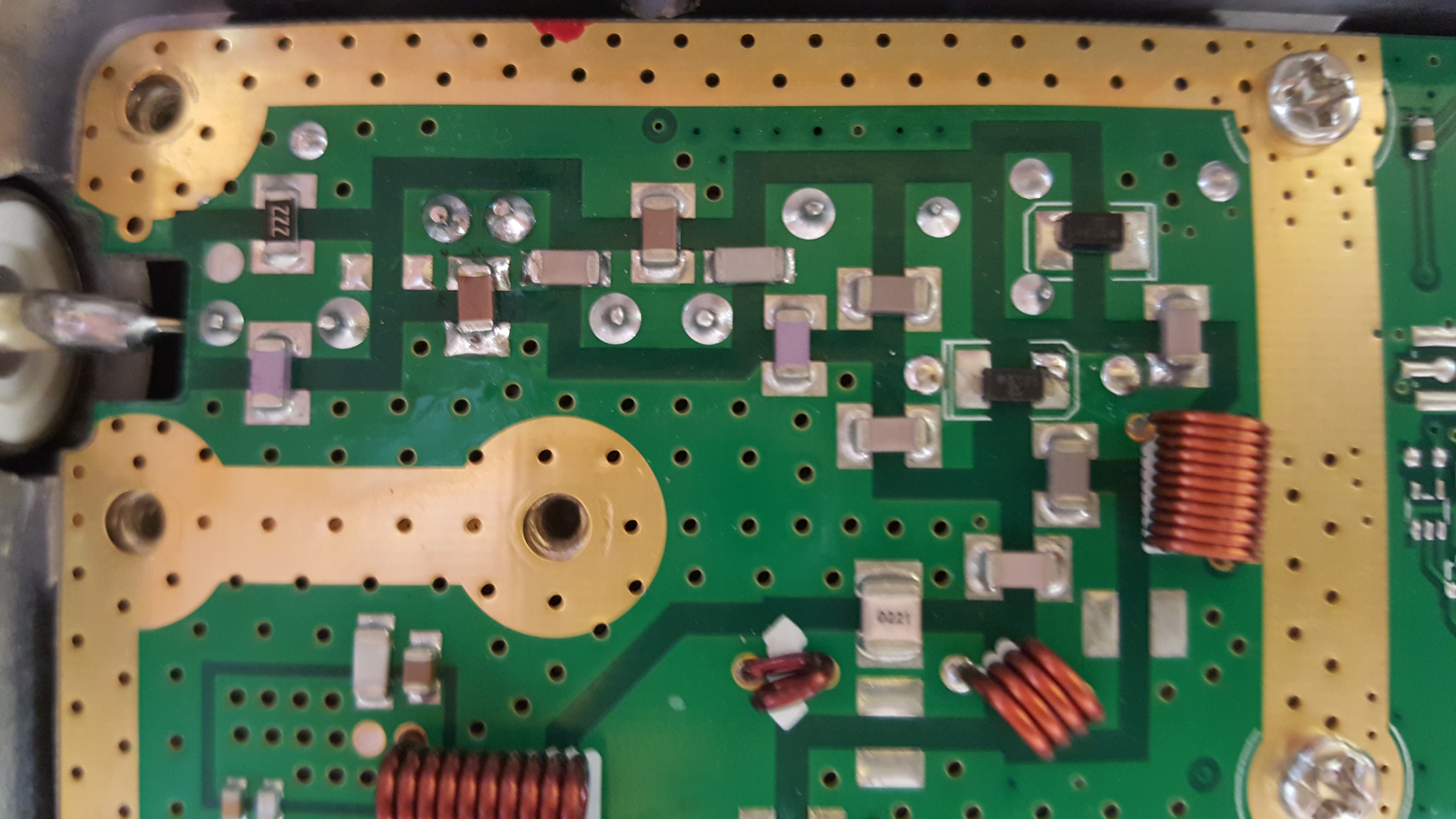
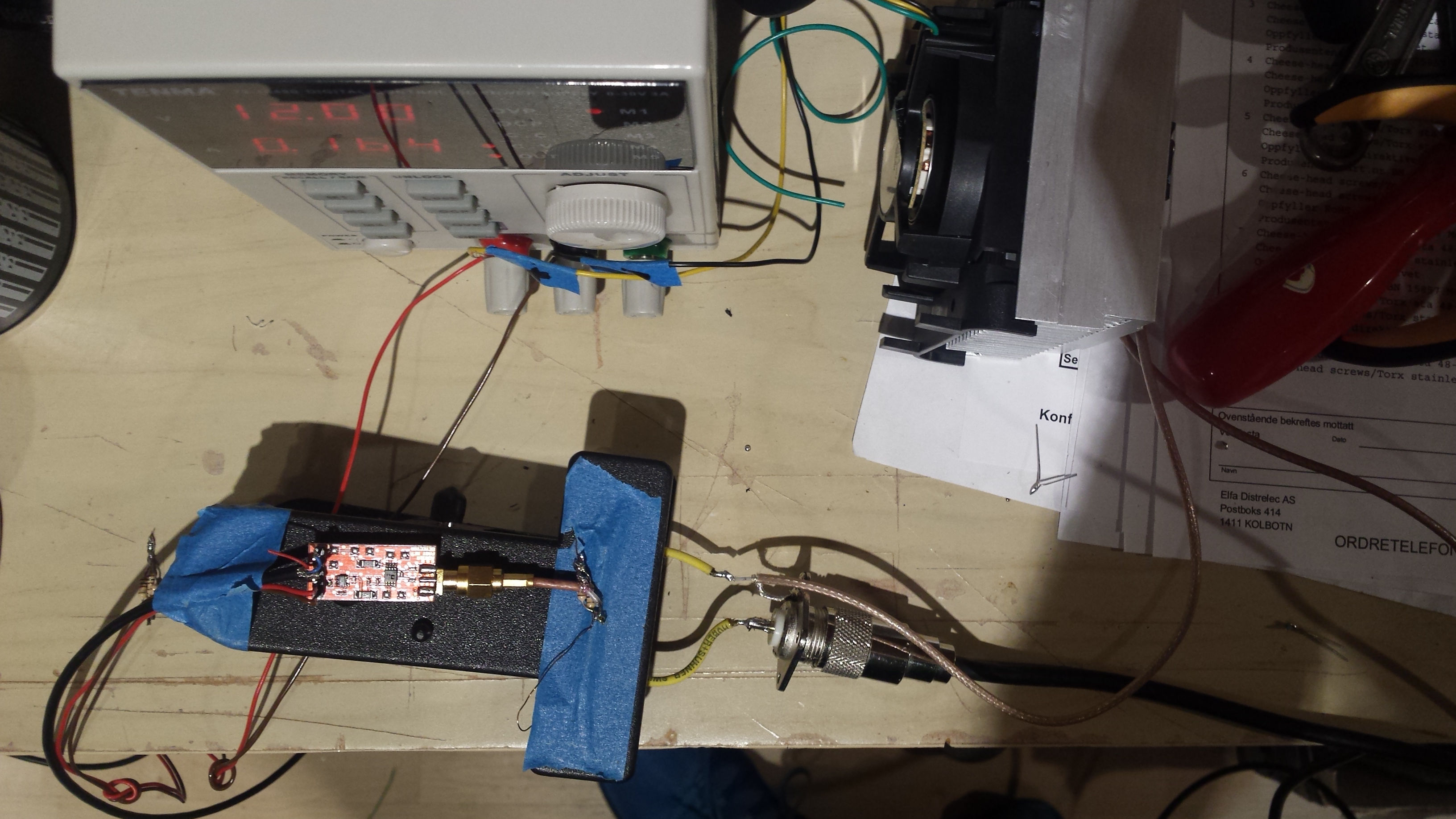
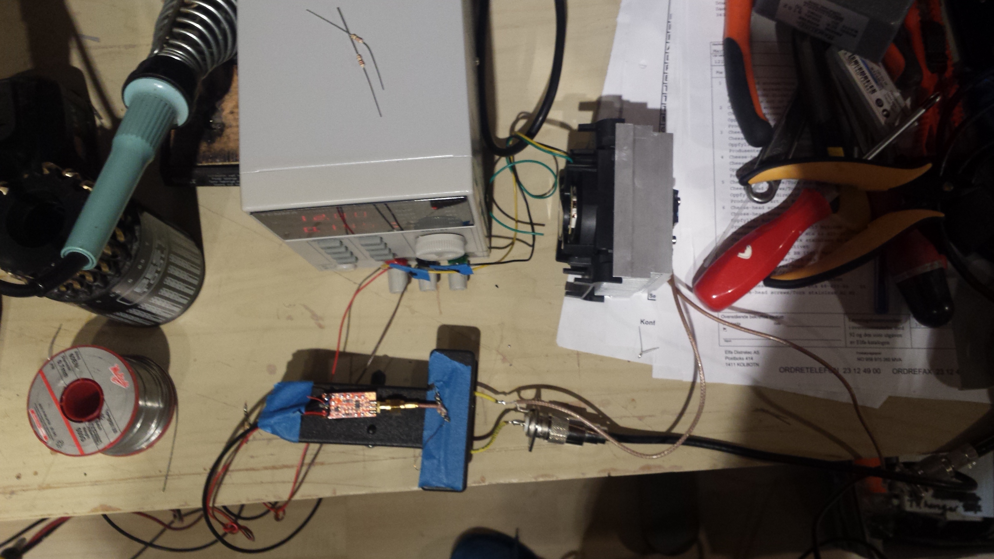
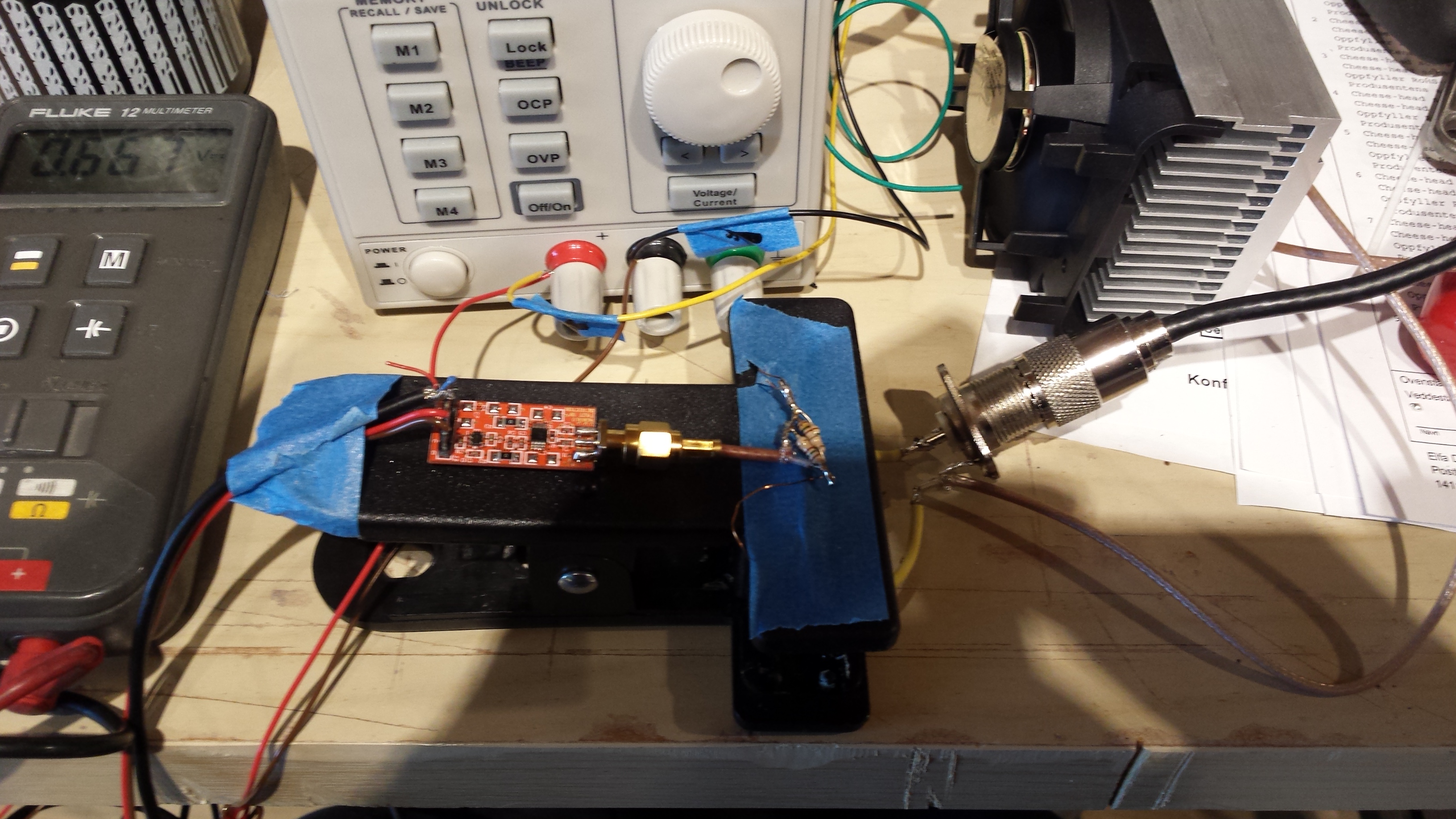
The Red Pitaya SDR board is based on the Xilinx Zync SOC and has 14 bit external A/D converters. However, for SDR usage on the HF bands from 0.1-30 MHz (and for that matter up to 50 MHz) the Red Pitaya is a bit “deaf” in the stock configuration. I have made a broadband amplifier that has a fairly high gain and very good IIP3 properties. Below I have posed some pictures of the prototype amplifier.

20160424_153046-1
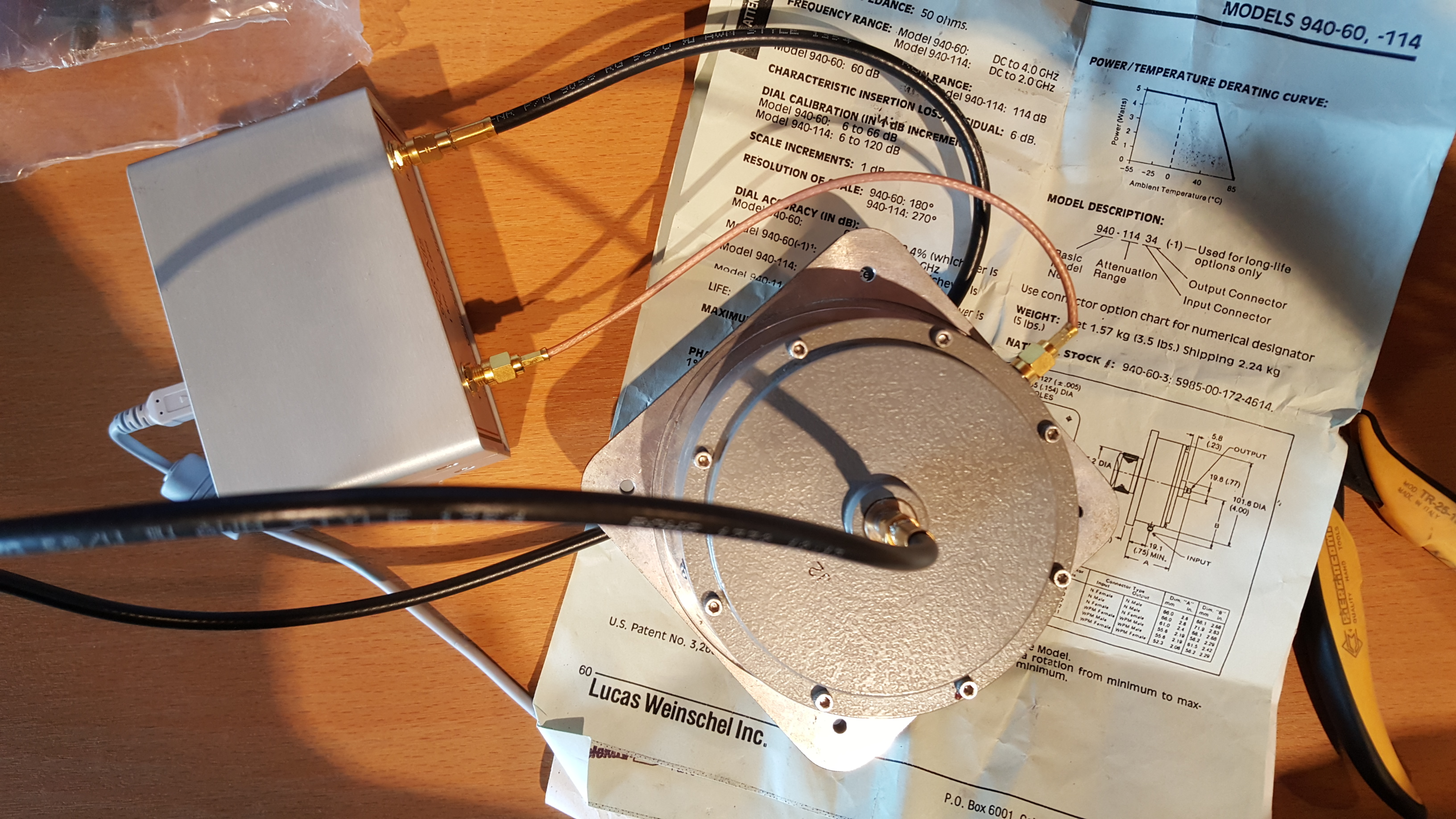
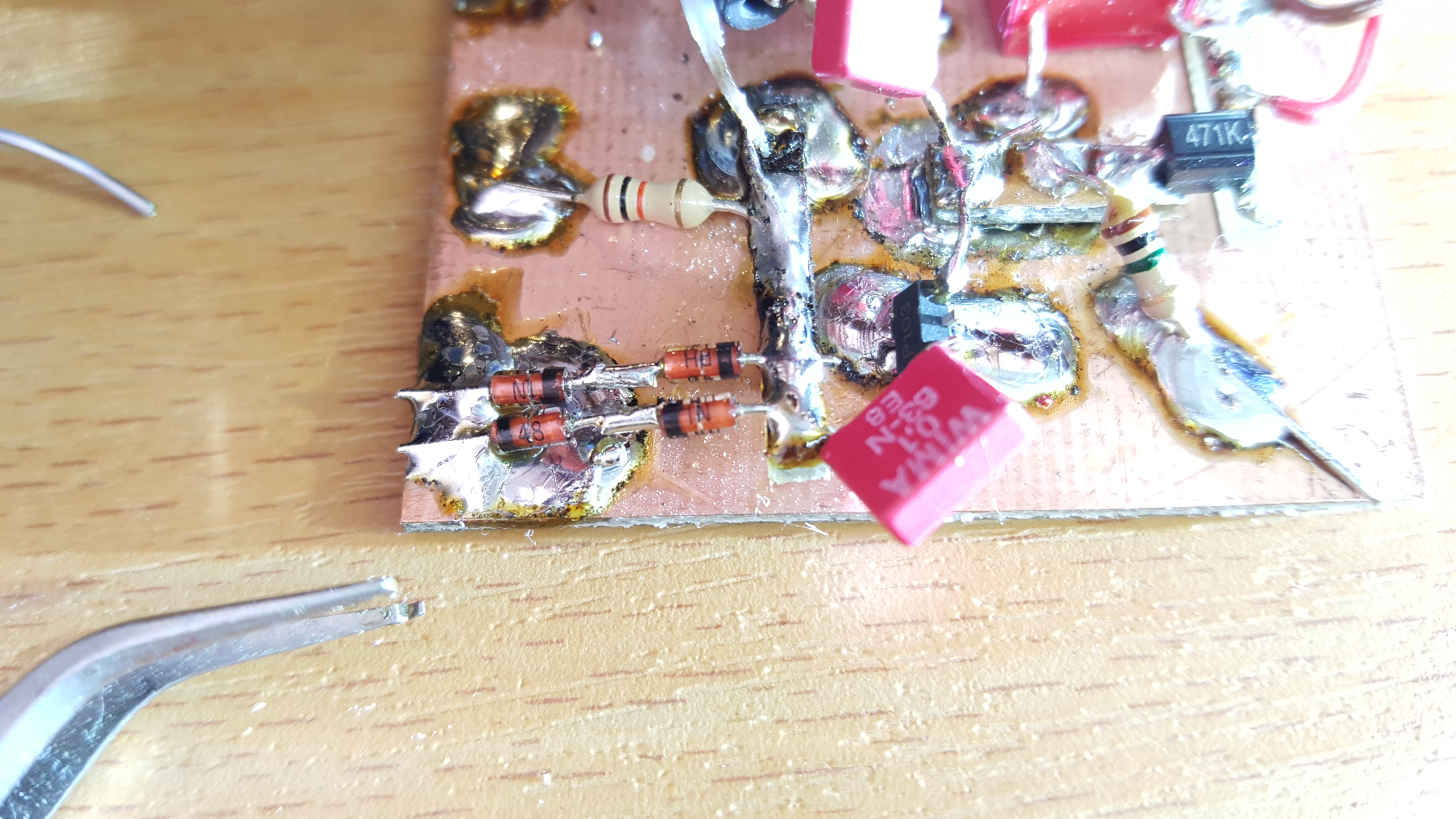
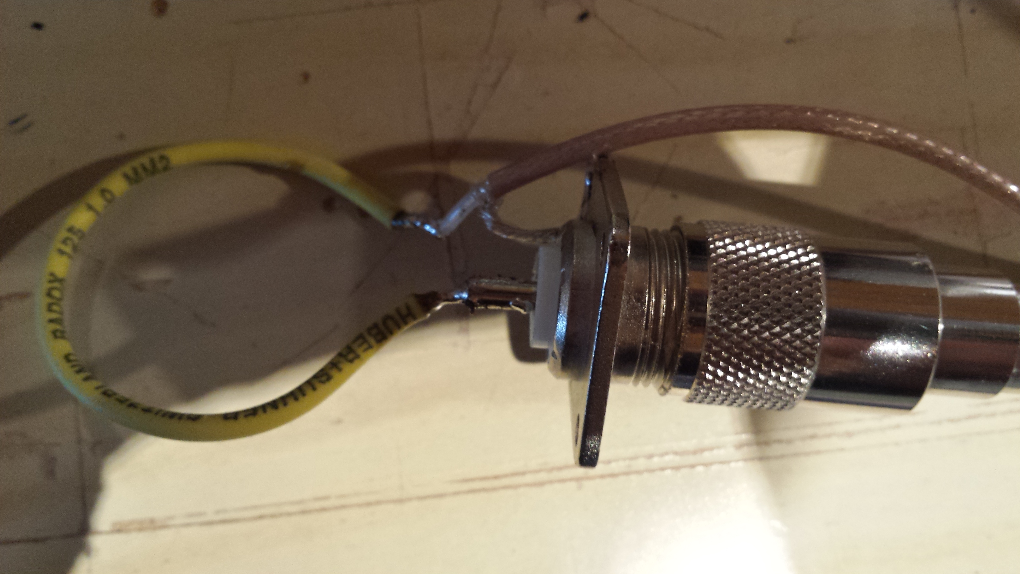
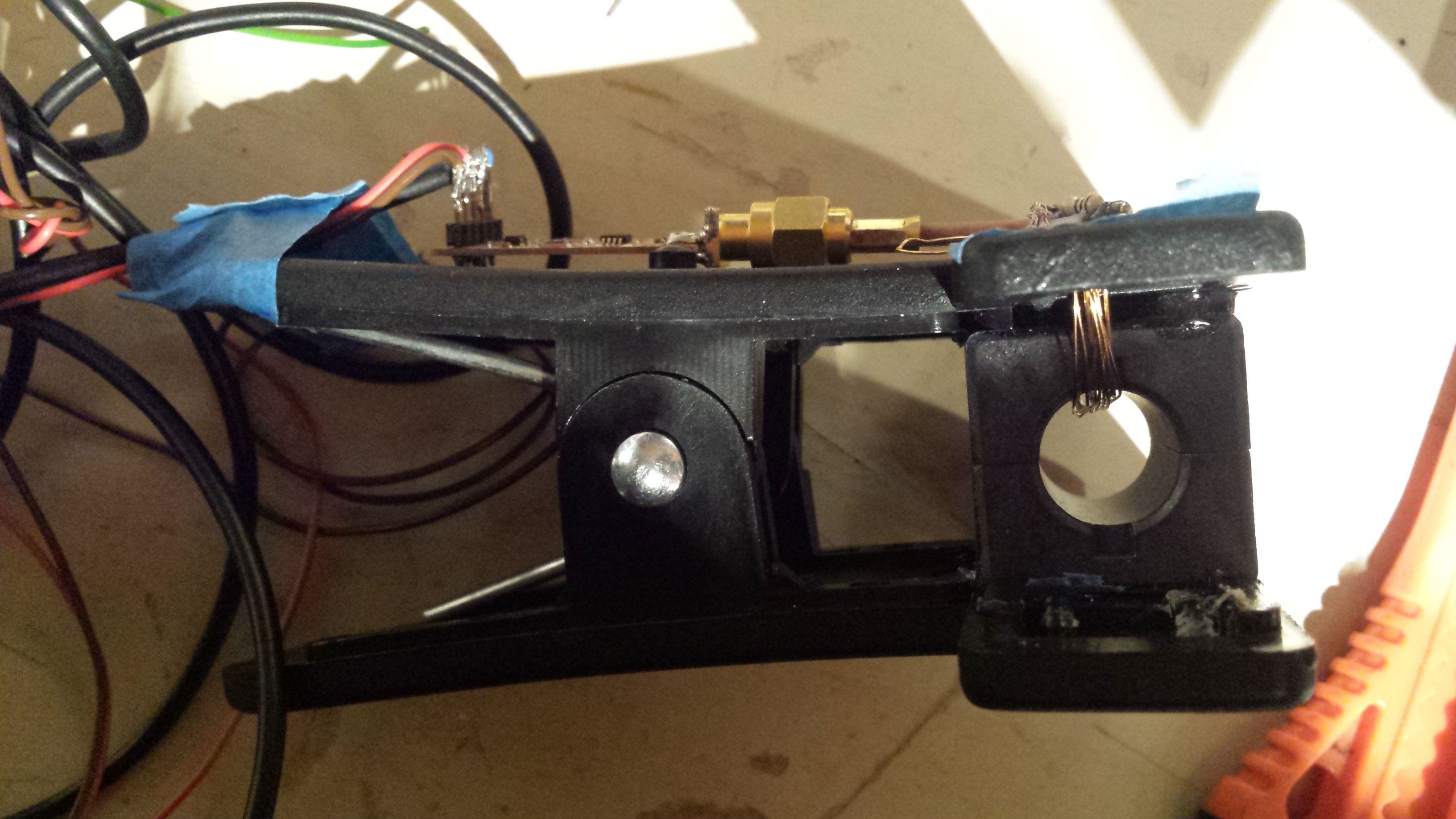
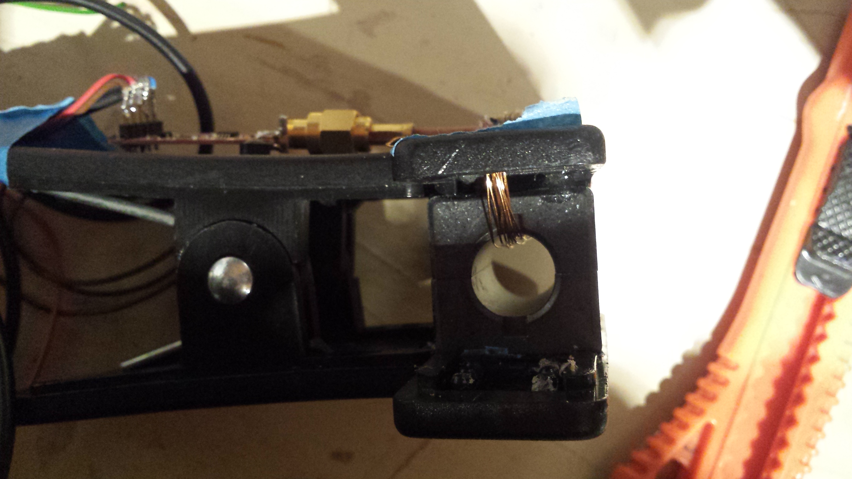
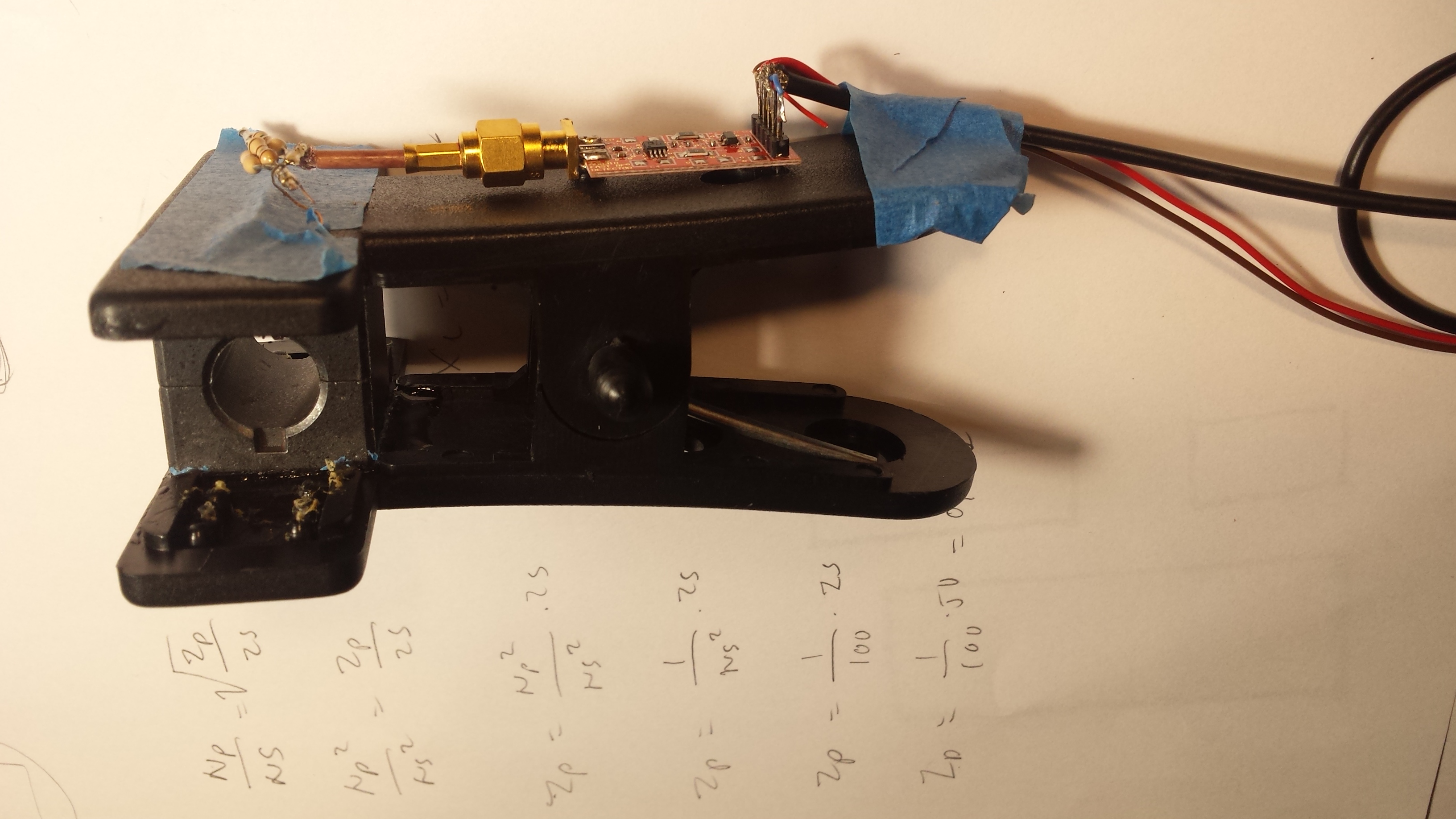
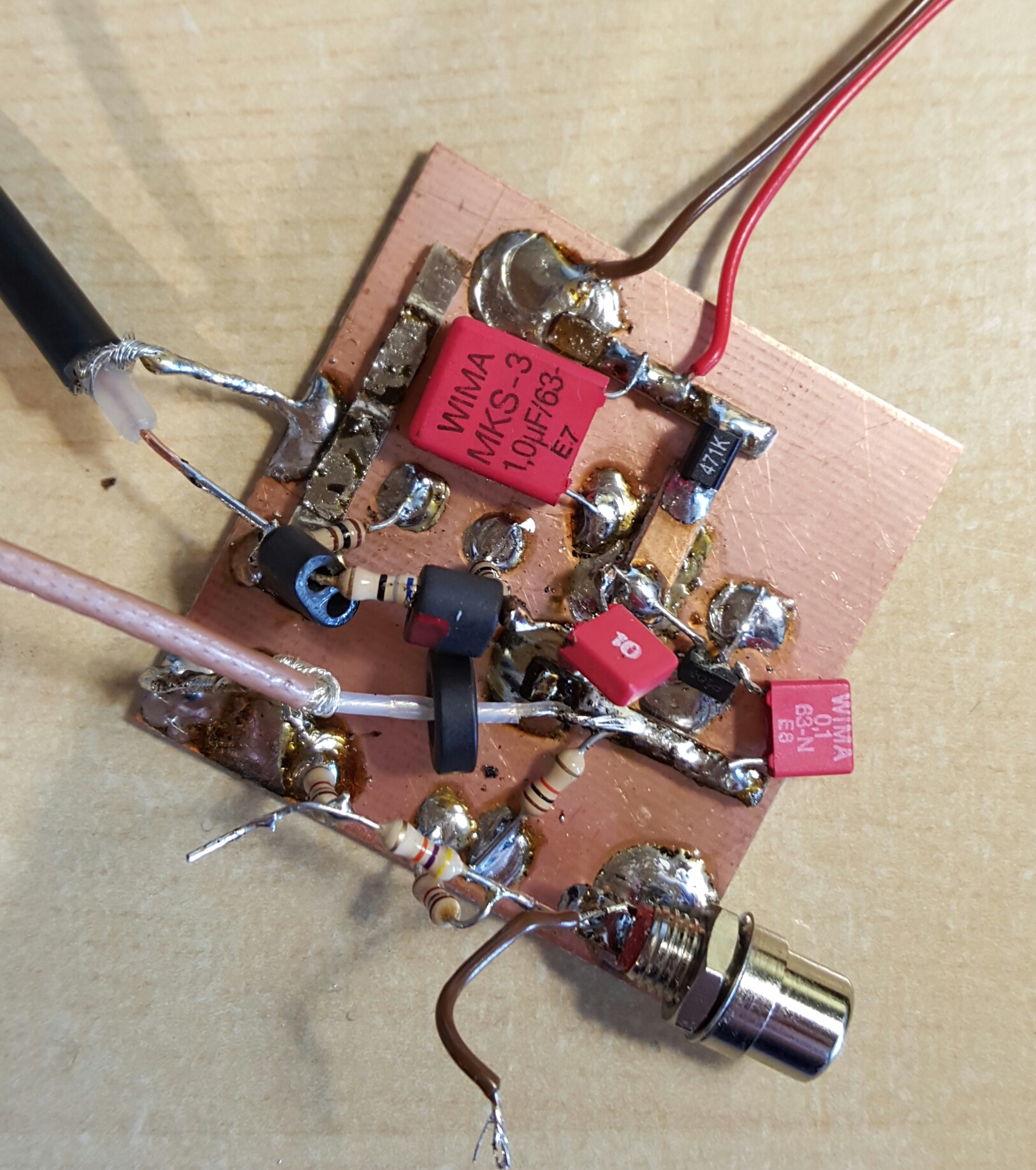
This is the prototype amplifier. I inserted a ferrite ring on the input lead to roll off the VHF / UHF sensitivity to reduce problems with nearby broadcasters etc. There is a also a PI network attenuator on the ouput and I have inserted a couple of beads in that as well to roll of the outpu response when frequency increases. The other components in the lower part is a input pi attenuator I used when I did some VNA frequency response measurements. This as well as the RCA plus is not used (RCA plugs are surprisingly good for low level RF signal routing in the HF bands and nice to use in the lab).  I used a more professional attenuator with a large attenuation range and flat response to determine the proper attenuation level after the preamp into the Red Pitaya. Reducing gain after the first amplifier has very little effect on the noise figure. Reducing it before the first amplifier directly adds to the noise figure. I added some protection diodes over the input to reduce the risk of strong RF signals or static voltage build up damaging the input. Below I am measuring the response of the attenuator with the DG8SAQ VNA. It was flat from 0-1,3 GHz.

20160424_203234-1

20160424_14035020160424_232930


Red Pitaya SDR TX / RX

The Red Pitaya hardware is the first low cost RX / TX capable SDR hw to come onto the market that is open source and can match the Ettus Research USRP periperhal. It has a combined CPU and FPGA signal chain with  two channels 14 bit 125 MSPS A/D and D/A. It also has a Dual core ARM Cortex A9+ FPGA (Xilinx Zynq 7010 system on chip). Only a few years ago this caliber of hardware had to be custom designed and was typically used in radar antijamming systems, radar signature classification systems, ultrasound, sonar and in high end vibration analysis tools (as examples). The ARM CPU on board can run Linux and it has GNU-Radio support. For fast data transfer there is a GBE (Gibabit Ethernet) interface to other host systems. With a a RTOS on the ARM core or a zero copy IP stack under Linux it should be possible to approach fairly close to 1 Gbit/sek transfer rates to host systems (if needed).
References:
http://www.rs-online.com/designspark/electronics/eng/nodes/view/type:design-centre/slug:red-pitaya
http://wiki.redpitaya.com/index.php?title=Hardware_Overview

20160408_14423420160408_144812

533c13a78bf449debc9d183e0ab30198600px-RedPitaya_HW_architecture

Teardown of the AnyTone AT-5189 4m FM radio

I purchased a couple of Anytone AT-5189 4m FM radios at a flea market. As the radio is of Chinese origin I was interested in seeing how the chinese engineers is coming along regarding design, waterproofing / IP degree, PCB layout, internal shielding, component selection and general workmanship.

Summary: the radio is surprisingly well designed. A cast alu chassis is made with milled grooves for O rings, professional layed out PCB,  proper ground vias and compartmentization,  no stray cabling inside. The integrated chips used in the design are LMX1511 synthesizer, MC3311 compander, M62364 DA, KIA278 LDO, RDO7MVS18 driver. Well known integrated circuits.

Some pictures:

20160410_084411-1 20160410_084351-120160410_084451-120160410_084808-120160410_09443120160410_084402 20160410_094318

20160410_084127-120160410_084430

HDSDR trackerball VFO project

I have been working on a trackball based controller for my HDSDR SDR project lately. This is a small R&D project that is run on my spare time where the goal is to determine if it is possible to use a trackball as a VFO for software defined radio (SDR) in contests. The project started out based on a demand for a more ergonomic way to operate a mult receiver in a contest environment that is less fatiguing during 48hours duration of a major contest like CQWW or CQWPX. The goal is that it should be possible to operate all radio functions you need from one hand only: VFO, speed of vfo, band, mode, filter width, volume, gain. I have modified a Marconi trackball and the controller is a Trinket Pro controller (Arduino)

20151219_131116 20151219_130846 20151219_123341 20151219_163343
20151217_211347 20151217_211710

20151219_153628


Repair of LDG automatic antennatuner

I blasted my LDG antennatuner some time ago. Or …. I thought I blasted it….. It appeared that it was only the resistor in the SWR detector circuit that got burned out. I replaced that resistor and now its ok again.It was easy to repair. However these small LDG tuners dont take more than 100W max. The designers have used ferrite cores, whereas it would have been a much better idea to use carbonyl cores or air core inductors. The latter doesnt get so easily saturated.

20150828_113855 20150828_102444 20150828_102215 20150828_101339

However I must say that the design of the LDG equipment I have seen so far is not very impressive. Why use that BIG chasis when you dont need it? Why use DB9 style connectors on a chassis that is supposed to be watertight? Look at that coax termination there. Both on the board and on the PL259 chassis connector. Why use RG174 teflon coax when you have such crappy terminaions? Perhaps it would be better with no coax at all 🙂 However when the tuner works it works fairly OK. Just dont trust this kind of equipment in a contest or on a dx expedition.

RF current amperemeter with log detector

I have long had the need to measure antenna current. This can be done by a rf-current transformer and a rectifier made by a shottky diode or fast silicon diode and an integrator driving a mechanical instrument. However the dynamic range is very limited with such a setup.

Therefore I made a new rf-amperemeter design with a log detector chip from Analog Devices driven from a current transformer made out of a split core ferrite material that has response in the HF and lower VHF frequency range.The current trafo is terminated in a few ohms and the RF current conductor (actually the primary) sees only a fraction of an ohm so very little influence is done on the circuit you are measuring. (Apart from capacitive coupling and a slight leakage inductance from the current transformer windings/ferrite combination). The ferrite core is a split type and is epoxied to a clip.

I calibrated the instrument by terminating the generator in a fancooled 100W dummy load and measured the voltage over the load by an oscilloscope. Since it has a log output the dynamic range from milliamp range up to 1,4A RF current. That would peg a mechanical instrument if you would at the same time want to be able to detect a significantly lower RF-current without having to change scales with switches / pot meters etc.

Next I plan on making a OLED display on this design with an arduino controller. Its a sparetime project so lets see how long tiem it takes before I implement that.

20151028_171941 20151028_171934 20151028_123754 20151028_123344 20151028_123330 20151028_111539 20151028_111534 20151027_222849 20151027_222832 20151027_222828 20151027_222353 20151027_222327 20151027_193055 20151027_151301 20151027_151250 20151027_123354 20151027_123343 20151027_123332 20151027_112816 20151027_112802 20151027_112746

A MIL-SPEC roller inductor for QRO operation

I recently got hold of a motorized roller inductor that is made PROPERLY. This is a MIL-SPEC unit that has been on stock for many years. It features a silver foil that is rolled on to a ceramic former, pretension, a shortcut cylinder that prevents eddy currents and arcing on the unused coil section under QRO operation. Due to that the unused coil is shorted and that the shorting is not a single turn, that the foil is wide, this coil has a very high Q.

DSC_9779DSC_9776

Single Sideband (SSB) modulation on the Raspberry PI

F5OEO has recently written some code to transmit a SSB signal using just the hardware in the Broadcom SOC chip on the Raspberry Pi.  You can find more info on this link http://www.rtl-sdr.com/transmitting-fm-am-ssb-sstv-and-fsq-with-just-a-raspberry-pi/

I tested the code on my RPI on 6m via a cable connection. It worked OK. If you look at the S-meter you can see that the envelope is constant. This is due to that the RPI has no way of modulating the envelope so the software actually modulates frequency. It is kind of constant envelope SSB.

Below you can see what the signal looks like. (This is received on a SDR via an attenuator). The signal is a bit too wide. However cool test.

20151101_214334
If you want to test the code yourself you can check it out over on F5OEO at github https://github.com/F5OEO/rpitx

Warning: do not connect the RPI GPIO output running this code to an external antenna without a bandpass or lowpass filter and a valid amateur radio license. Never transmit any signal outside the amateur bands.

Very big QRO rolling inductor

I just got myself a new roller inductor. This one is designed on the principle of a silver foil that is rolled away from and onto a ceramic form with guides for the silver form. The ceramic coil forms the coil. There is a large shorting cylinder that the unused silver foil is rolled onto. The effect of this is to significantly increase the Q of the inductor. For high power QRO applications there may either be arcing from the end of the unused part of the coil or heat loss in this part of the coil. How the unused coil is completely shorted with an inner conducting cylinder and the unused part of the coil has no flux thru it.

rullespole_indrullespole_type_STOR_QRO